Geometry and orientation
Wall thickness, overhangs, support, visible faces and interfaces affect orientation and preparation.
Choose a printing plan around what the part needs to do. We review geometry, material preference, quantity and finish before confirming the manufacturing scope.
Wall thickness, overhangs, support, visible faces and interfaces affect orientation and preparation.
Material availability and suitability are reviewed against the stated job; no one material fits every requirement.
Visible layers, support marks, joining, inserts and post-processing should be included in the scope.
No. Requirements are reviewed for the selected process, material and geometry.
FDM has a visible layer structure. Any additional surface preparation must be agreed separately.
Large assemblies may need subdivision and joining. One-piece limits are confirmed from the selected equipment and orientation.
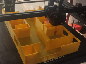
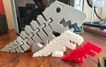
The tray photograph shows thin walls and repeated compartments; the skeleton image shows flat interlocking pieces. For comparable geometry, identify which faces must remain clean, which connections must fit and whether pieces are printed separately. Orientation, support removal and layer direction belong in the manufacturing plan.
The photographs illustrate geometry; they do not establish a material grade, tolerance or functional test result. Prepare material and finish requirements.
Plan board mounting, connector access, cable space and lid closure around the complete assembly, with a copyable enclosure brief.
Count parts and sets, define the first-part approval, control revisions and plan packing before repeating a prototype across a batch.
Plan split lines, alignment, visible seams and packing before a large printed model becomes a collection of separate components.
Mark the faces that will be visible, the interfaces that must fit and any thin or unsupported features. Ask the quotation to identify the selected material grade, orientation and support/finish scope. State quantity per unique part rather than only the number of assemblies.
A layer setting does not by itself guarantee overall accuracy. Define critical dimensions and the agreed inspection method for your actual part.